Digitizations and Transformations
To begin, I create three feature classes in my project’s geodatabase: Landmarks (points), Buildings (polygons), and Roads (lines). For good measure, I ensure that the classes share the same coordinate system. A “Name” field is added to each class for easier identification. Of the three, creating the campus landmarks is the most straightforward and comparatively effortless. I plot four points across the map. The second class that I will visualize are roads, starting with Charles E. Young Drive North. Allow me to share some 'roadblocks' that require attentiveness to detail. Creating turns that properly align with the road may take several tries. Even more frustrating is the .tif layer. As I zoom into the road to get a better sense of accuracy, cloud overcast and shadows become visible. I make sure to fill in a name for the street before constructing the lines. Surprisingly, there exists three Charles E. Young Drives with distinct cardinal directions (North, East, West) that do not connect with their counterparts. To distinguish them from one another, I modify their symbology with the label “2” after their names. The final class, buildings, may prove to be the most difficult part. Trees and shadows in the .tif file obscures corners of the buildings, and since the imagery is not truly top-down, at times both the top and side of the buildings are shown. To get around this, I will digitize buildings that are visually clear. After digitizing 20 buildings, I begin the spatial adjustment process. Inserting the UCLA_Blocks layer indicates that they are way off course from proper alignment. I use the Transform tool (Edit->Modify) and check the UCLA_Blocks shapefile under the Layer panel. I can then press “Add New Links”. I connect both layers using the corners of buildings, even using off-campus points for greater accuracy. At the end of the process, there were over 100 links (after checking “Affine Transformation” and clicking “Transform”).
Misalignments
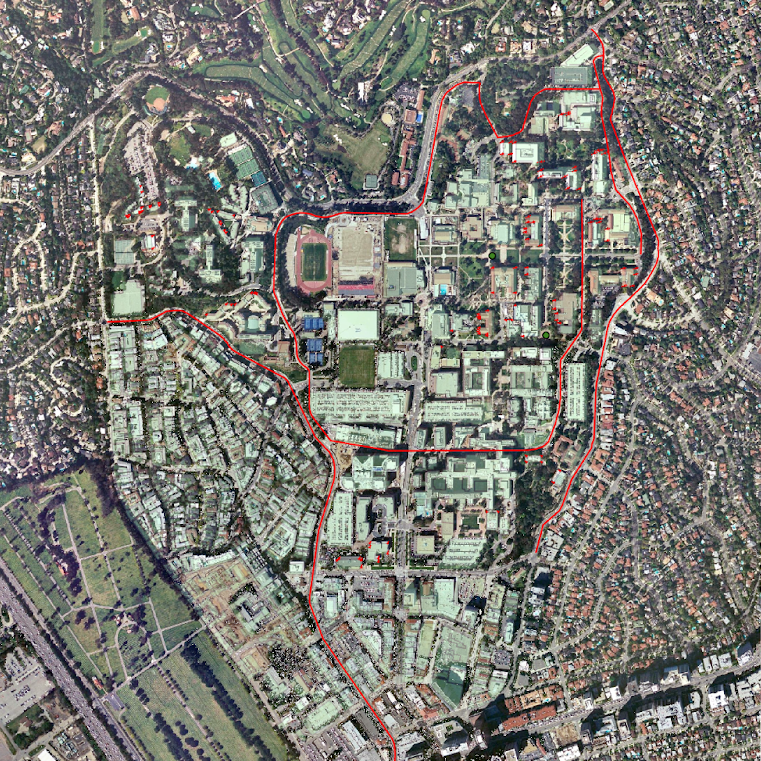
After the spatial adjustment process, the feature classes and layers neatly match. There are still a few misalignments between the digitized buildings and the transformed UCLA_Blocks shapefile. Fixing irregularities at this point would certainly feel tedious; I would have to link many more buildings to ensure that the rest of the map isn't interrupted. Down the road I will show the steps for spatially adjusting one building at a time, without automatically transforming other buildings. Overall, I would wager that 95% of the buildings lined up correctly. Those that did not properly align were irregularly shaped and larger than their counterparts.
Snap Tool vs. Interactive Building Tool
The “Snap” tool automatically aligns features using their respective inputs. It is found under the Editing toolbox in Geoprocessing. Select a suitable “Type” for the task at hand, either “End”, “Vertex”, or “Edge”. In other words, the vertices of the inputted feature will snap to either the end, vertex, or edge of the feature class. The tool can accept multiple layers; again, ensure that they have the same coordinate systems. Select a distance and respective units, or click “Unknown” for the tool to calculate it automatically. The “Distance” tab determines the space that the verticies snap onto the selected "Type", either as an end point, edge, or vertex. The interactive building tool requires at least three links between corners. For maximum accuriacy, ensure that the “Snapping” option is checked. Using this tutorial's example, I select a corner of UCLA_Blocks and a corner of the .tif layer. The interactive building tool has multiple transformations to choose from. The affine transformation can scale, skew, translate, and translate the data. This is distinct from the similarity transformation, which scales, rotates, and translates the data. The project transformation requires four links minimum. Overall, the Snap Tool is semi-automatic (users simply fill out the tab to their choosing) while the interactive building tool is manual.
Rubbersheeting
Found under the Conflation toolset, Rubbersheeting is an editing tool where users can adjust features post-transformation. Ideally, a user should rubbersheet if the input feature class does not align with the most accurate layer. It uses spatial adjustment to achieve a more suitable alignment. The tool can only be used after generating Rubbersheet Links. There are two transformational methods of rubbersheeting: linear and natural neighbor. Linear rubbersheeting is the faster method, ideal for links that are evenly spread out. Natural neighbor rubbersheeting is slower but more accurate. If the distance between links shows no uniformity, then natural neighbor is your best bet.